Hi Scott,
Which motor do you have ? What Supply voltage?
Actually the max allowed Amplitude value is 230.
That Amplitude will basically relate to a fixed applied voltage.
Are you sure your commutation is working correctly? You might command a small Amplitude and hold the motor with your hand. At any shaft angle the torque should be approximately the same.
Those motors appear to have fairly low resistance (0.38 ohms). Suddenly applying even 12V when the motor is stopped with no back emf would generate 30+ Amps of current. So you may need to gradually increase the amplitude the way a servo and acceleration trajectory would.
Regards TK
| Group: DynoMotion |
Message: 11822 |
From: cnc_machines |
Date: 6/29/2015 |
| Subject: Re: BDC Hall Motor |
|
Tom,
Thanks for your response I am using the motor highlighted in yellow with a 40V power supply.
I was unaware that the motor would fault so quickly with an overcurrent. I was hoping to drive this motor fairly hard. Is there a way to monitor the current and adjust the PWM to keep the max power at a given speed without faulting?
Scott
|
|
|
@@attachment@@
|
| Group: DynoMotion |
Message: 11826 |
From: Tom Kerekes |
Date: 6/29/2015 |
| Subject: Re: BDC Hall Motor [1 Attachment] |
Hi Scott,
With only 6V/1000RPM back-emf a theoretical speed of ~6000RPM should be possible with 40V. Not sure why you aren't getting much. Did you do the commutation torque test I asked you to perform?
Applying a full 40V to a stopped motor of only 0.38 ohms the current would quickly rise to 40/0.38 = 105 Amps!
SnapAmp Peak current limits are designed to respond in microseconds to protect the FETS from a short circuit.
There are many approaches you could take. I think the best is to configure a Servo Axis so you can perform controlled acceleration and the servo error will apply the voltage as required to accelerate and maintain speed.
Regards TK
| Group: DynoMotion |
Message: 11829 |
From: cnc_machines |
Date: 6/30/2015 |
| Subject: Re: BDC Hall Motor [1 Attachment] |
|
Tom,
I set the amplitude at 10 and griped the shaft. As it rotates the torque feels fairly constant through the whole 360 degrees.There is some vibration on the shaft in different locations, but there is still torque.
When I hold the motor rotating slowly it does not feel completely smooth either, It almost feels like it is jerking a little bit. It feels similar as I increase the speed, maybe this is what is causing the problem?
I am not sure what else to check for. I have changed the hall sensor combinations to every other arrangement and get no rotation at all. Do you know what hall spacing the example program was designed for? I believe the motor is 120 degree angle spacing. Could this be the problem?
Thanks,
Scott
|
|
| Group: DynoMotion |
Message: 11831 |
From: Tom Kerekes |
Date: 6/30/2015 |
| Subject: Re: BDC Hall Motor |
Hi Scott,
The "Vibration" doesn't sound correct.
There are many many ways to set the hall sensor table. Have you really tried them all?
You might display the table values as they are used to verify the angle is indeed increasing incrementally with shaft angle. A trick I sometimes use to debug is to set the value of interest into an unused Axis Destination so I can view the value on the Axis screen. Such as:
ch7->Dest = CommTable[index];
or
ch7->Dest = index;
I don't know what type of motor the example was used with. It shouldn't matter as long as you build the table based on what hall sequence you actually see as the shaft rotates.
Depending on how many motor poles you should see a clean hall sensor pattern sequence that repeats 2 or 3 times per shaft rotation. Do you observe this?
HTH Regards TK
| Group: DynoMotion |
Message: 11833 |
From: cnc_machines |
Date: 7/1/2015 |
| Subject: Re: BDC Hall Motor |
|
Tom,
I will work on this today.
ch7->Dest = CommTable[index];
Where do I go to see where this is written? Does it write out to the console, or the step response screen or something?
Thanks,
Scott
|
|
| Group: DynoMotion |
Message: 11835 |
From: cnc_machines |
Date: 7/1/2015 |
| Subject: Re: BDC Hall Motor |
|
Nevermind.. just found the axis screen.
|
|
| Group: DynoMotion |
Message: 11837 |
From: cnc_machines |
Date: 7/1/2015 |
| Subject: Re: BDC Hall Motor |
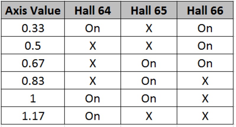
Index
Hall 64
Hall 65
Hall 66
0.33
On
X
On
0.5
X
X
On
0.67
X
On
On
0.83
X
On
X
1
On
On
X
1.17
On
X
X
I dont really understand what the changing index value is doing. Do these numbers look correct?
Thanks,
Scott
|
Tom,
I apparently dont fully understand how this program works. When I very slowly rotate the shaft I get the following values off of the Axis screen, and the hall states from the digital IO.
|
|
| Group: DynoMotion |
Message: 11846 |
From: cnc_machines |
Date: 7/1/2015 |
| Subject: Re: BDC Hall Motor |
|
Just saw that the formatting did not go through with this. Here it is again as an image.
|
|
|
@@attachment@@
|
| Group: DynoMotion |
Message: 11848 |
From: Tom Kerekes |
Date: 7/1/2015 |
| Subject: Re: BDC Hall Motor [1 Attachment] |
Hi Scott,
Sequence seems reasonable. One transitions off, then one on, then off, then on, etc...
See attached:
The commutation increases in a monotonic manner (1.17 cycles is the same as 0.17 cycles). You might try adjusting the Commutation Offset by varying amounts to see if you can get some improvement. I'd initially try increments/decrements of 0.05 to see wat happens.
Regards TK
| Group: DynoMotion |
Message: 11851 |
From: cnc_machines |
Date: 7/2/2015 |
| Subject: Re: BDC Hall Motor [1 Attachment] |
Tom, I have made some progress here. As I rotated the motor shaft I noticed that randomly the index would drop to zero. I think this is what was causing the random ticking and vibration in the axis. I had the halls plugged in to the encoder inputs (64, 65, 66). I changed these to the Opto isolated inputs(72, 73, 74). The motor definately goes faster now, though max RPM is still less than 1,000 and it has a constant vibration - not the random one. Would I have been better off pluging in to the LVTTL inputs? They are 5V hall sensors. Or would the opto inputs have just as good of a response time? I am still struggling to understand how the Write3PH(ch,A,CommTable(index)) is working? - "put a voltage on a three phase motor at a specified commutation angle"
- Is this in degrees?
- What are the max and min possible values?
- How are the thee motor winding excited based off of this number?
I am thinking if I understood this better I could troubleshoot the problem. I should be getting a much faster speed without the vibration. Thanks, Scott ---In DynoMotion@yahoogroups.com, <tk@...> wrote : Hi Scott,
Sequence seems reasonable. One transitions off, then one on, then off, then on, etc...
See attached:
The commutation increases in a monotonic manner (1.17 cycles is the same as 0.17 cycles). You might try adjusting the Commutation Offset by varying amounts to see if you can get some improvement. I'd initially try increments/decrements of 0.05 to see wat happens.
Regards TK
| Group: DynoMotion |
Message: 11855 |
From: Tom Kerekes |
Date: 7/2/2015 |
| Subject: Re: BDC Hall Motor |
Hi Scott,
index dropping to zero would mean that your Hall sensors are not interfaced correctly. There should never be any invalid states. As you can see from your previous table only one hall should change at a time (sort of like gray code or A B quadrature so no invalid states even when sampled right when transitioning).
You didn't provide the interfacing information on your Hall Sensors but I searched and found this:
It seems the Hall Sensors are Open Collector. Did you realize you would need pull up resistors?
They are not differential signals so they shouldn't work connecting to differential inputs
The SnapAmp Opto Isolated Inputs were not intended to be high speed signals.
You should be better off with the faster KFLOP inputs. Probably with 330ohm pull up resistors to 3.3V.
Regarding Whrite3PH:
The angle is specified as a fraction of a cycle. So 0.0 would correspond to 0 degrees and 1.0 to 360.0 degrees. The value may be greater than 1 or less than 0, in that case only the fraction is used.
Basically the voltage applied to each lead is equivalent to:
Lead A = Amplitude x sin(Angle) Lead B = Amplitude x sin(Angle + 120 degrees)
Lead C = Amplitude x sin(Angle + 240 degrees)
HTH Regards TK | | | | | | | | | | | |
.png)